237
configuration, such as an electric-drive motor, bearing assemblies with a lubrication sys-
tem, a rotating shaft seal with a cooling system, and a flow part.
Each power unit with VVER-1000 reactor is
equipped with four primary coolant pumps – together
with a DN850 primary circulation line; each primary
coolant pump forms a loop of the primary circuit.
The primary coolant pump is mounted inside
the containment in the «cold» pipe run of the primary
circulation line and supplies water (primary coolant)
cooled in the steam generator to the reactor.
In accordance with the safety classification, the
primary coolant pump is classified as the equipment
operating in normal conditions. At the same time, it
has an additional function – it ensures coolant circula-
tion when running down in various emergencies with
power failure and, thus, provides for the seamless
transition to the natural circulation.
The primary coolant pump is designed so as to
provide for:
•
hot standby of the primary coolant pump – it
activates a reverse flow mode, if the anti-reverse rota-
tion mechanism is intact;
•
startup and steady operation of the primary
coolant pump with any combination of the operating
pumps in the reactor unit;
•
positive suction head in all transient condi-
tions in the reactor unit;
•
shutting down (running-down) of the primary
coolant pump without a damage in case of interrup-
tions in cooling and seal water supply;
•
primary coolant pump pressure pulsation and
vibration level, which does not result in failures in the
pump and systems associated with it;
•
prevention of radioactive coolant leakage in-
to the environment through the pump shaft seal;
•
absence of flyaway elements, which would be hazardous for the operation of the
reactor unit, if the pump is destroyed (in any anticipated mode);
•
components made of austenitic steels, which are not susceptible to inter-
crystalline corrosion;
•
use of materials of components operating in contact with the coolant, which are
free of cobalt and other specific elements forming long-lived isotopes in the active operat-
ing fluids;
•
reparability of the primary coolant pump – the pump must be separable and its
components must be replaceable. The pump shall be designed so as to provide for the re-
placement of most units of the primary coolant pump and their separate elements. At the
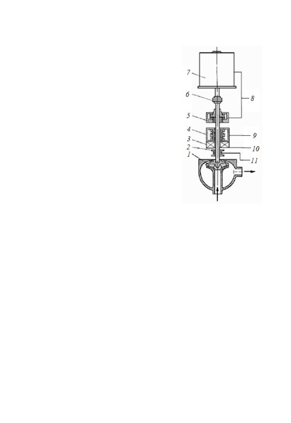
Fig. 5.3. Schematic Diagram of the
Primary Coolant Pump with a
Mechanical Shaft Seal:
1
– Flow part of the pump;
2
– Bot-
tom journal bearing;
3
– Refrigera-
tor of the shaft seal case;
4
– Shaft
seal unit;
5
– Combined journal
and thrust bearing;
6
– Coupler;
7
– Electric motor;
8
– Lubrication
system;
9
– Power supply system of
the shaft seal;
10
– Cooling system;
11
– Power supply system of the
journal bearing


