213
The vertical header is a cylindrical housing 1250 mm in the inner diameter with
an elliptical end 108 mm thick at its top. The bottom of the header is closed with a re-
movable cover. At the bottom of the header there are two pipes supplying and removing
coolant. The pipes are positioned at an angle of 120°. Inside the bottom portion of the
header there is a removable bush separating coolant inflow and outflow and preventing
coolant flow-over.
The part of the vertical header, which is inside the vessel, is formed by one
smooth and two perforated shells with the perforations into which the tubes of the heat-
ing surface are embedded. The perforations inside the header are arranged in a staggered
pattern at 40 mm intervals (upward) with the minimum interval of 23.27 mm on the in-
ner surface of the header. Further, there are several collars arranged one above the other,
which are used to mount and space heat surface screens.
The heating tube bundle consists of 330 pre-assembled screens, which are mounted
radially in the vertical plane. Each screen, in turn, consists of 36 operating 16×1.5 mm
tubes and two false tubes mounted on the outer and inner perimeter of the screen. The
tubes are made of austenitic steel. The tubes are
twisted around a line parallel to the header
axis – such design provides for the same length of
unbent tubes. Each tube has 16 bends to compen-
sate for the difference in thermal elongation of the
tubes and the header, and to make the heating sur-
face lower.
The end faces of the heat exchange tubes are
welded through perforations in the header to the
surfacing made on its inner surface and then rolled
into its wall using the explosive technique. At the
bottom of the tube bundle there is a pre-boiling
economizer range. Within the evaporation range,
the tube bundle is surrounded by a jacket 10 mm
thick. The design provides for a 60 mm gap be-
tween the jacket and the vessel wall, which is a
down-comer section of the free circulation line.
Further, there is a gap between the shell of the
economizer and the jacket, through which the cir-
culating water flows down from the down-comer
section to the bottom portion of the evaporation
range.
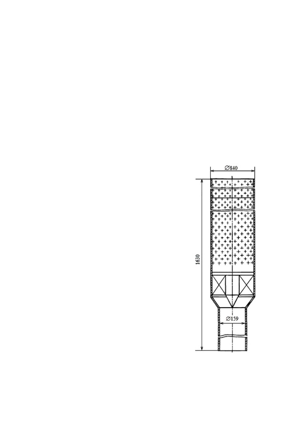
The centrifugal separator of PGV-250
(Fig. 4.18) has two separation stages. The first
stage with a bottom water inlet is formed by 156
centrifugal separators mounted on a conical baf-
fle in a triangular grid at 260 mm intervals.
The separator unit of PGV-250 is a perforated
shell 248×3 mm in the diameter with a perforated
area 1100 mm long. The shell has 2620 holes 6 mm in the diameter. At the bottom of the shell
there is a cyclone swirler and an inlet pipe welded to the baffle. Separators at the top of the
unit are welded together. The separator unit is braced – the brace is supported by a bracket on
Fig. 4.18. Centrifugal Separator of
PGV-250 Steam Generator


