105
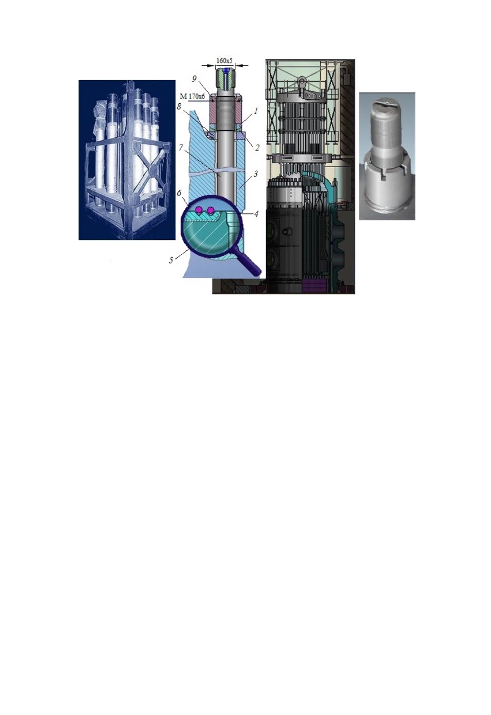
Fig. 3.10. Primary Seal:
1
,
2
– Washer;
3
– Head;
4
– Stud stretching control rod;
5
– Pressure vessel;
6
– Gaskets;
7
– Stud;
8
– Sector;
9
– Nut
The studs are tightened using a nut wrench with stud stretching and further free
complete tightening of nuts. The stud tightening torque shall be 20–25 % higher than the
force generated by the internal pressure to the reactor head. Such nut wrench is equipped
with hydraulic jacks, the moving parts of which are screwed onto protruding stud ends.
Under the effect of the operating fluid pressure, the jacks stretch the studs to a length re-
quired for proper tightening of the main joint. Stretching of the studs is controlled by a
measuring rod embedded into the internal stud cavity.
On the outer side of the pressure vessel, there is a support collar going below the
lower row of DN850 pipes. To position the reactor vessel as designed, the vessel is
mounted with the support collar on the thrust collar, where it is fixed with keys. There are
22 lengthwise cuts on the support collar of the vessel. These cuts are made to meet the
permissible railway clearance. The thrust collar is supported by the plates of the support
truss through 30 mounting groups. Each mounting group consists of double wedges, a lock
with a wedge, and two inserts. The wedges are used to fit the support ring to the required
height. The locks fit into the support ring and prevent it from turning and any other hori-
zontal movement. The reactor vessel collar rests on the gasket arranged on the support
ring. The above-mentioned keys prevent horizontal movement of the pressure vessel.
The reactor layout in the cavity is provided in Fig. 3.11.
The thrust collar (Fig. 3.12) is used to secure the reactor vessel in the concrete cavi-
ty. The collar is a machine-turned ring with slots for parts (keys) embedded into the con-
crete stand of the reactor cavity. The thrust collar is fitted on the reactor vessel flange us-
ing the wedges and on the keys embedded into the concrete stand using spike nails, which
are fitted at the installation site and welded to the keys. The mounting diagram for the
support ring is provided in Fig. 3.13.


